
Bluetooth Controlled Robot using Arduino
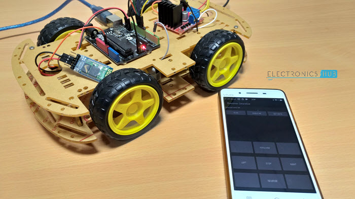
Photo:Electronics Hub;
In this project, I will show you how to design and develop a Bluetooth Controlled Robot using Arduino, HC-05 Bluetooth Module and L298N Motor Driver Module. On the other end of the Bluetooth Communication, I will be using a Smart Phone and a simple Android App to control the Robotic Car.
Components Required:
- Arduino uno R3
- Motor Driver - L293D
- Gear Motor x 2
- Wheel x 2
- Robot Chassic
- 9V Battery
- Battery connector jack
- Battery Cap
- Male to Male Jumper Wire
- Male to Female Jumper Wire
- HC-05 Bluetooth Module
- Android Phone
- Bluetooth Controller App

Robot chassis
Circuit:

Code:
#include<SoftwareSerial.h>

#define IN1 12
#define IN2 11
#define IN3 10
#define IN4 9
//#define EN1 6
//#define EN2 5

SoftwareSerial mySerial(2, 3); // RX, TX

String data;
int btVal;

void setup()
{
  //Serial.begin(115200);
  pinMode(IN1, OUTPUT);
  pinMode(IN2, OUTPUT);
  pinMode(IN3, OUTPUT);
  pinMode(IN4, OUTPUT);
  //pinMode(EN1, OUTPUT);
  //pinMode(EN2, OUTPUT);
  digitalWrite(IN1, LOW);
  digitalWrite(IN2, LOW);
  digitalWrite(IN3, LOW);
  digitalWrite(IN4, LOW);
  //analogWrite(EN1,63);
  //analogWrite(EN2,63);
  mySerial.begin(9600);
}

void loop()
{
 while (mySerial.available())
 {
  {
      data = mySerial.readStringUntil('\n');
      //Serial.print(str);
  }

    btVal = (data.toInt());
    //Serial.print("BlueTooth Value ");
    //Serial.println(btVal);


  switch (btVal)
   {
      case 1:
        //Serial.println("Forward");
        forward();
        break;

      case 2:
       //Serial.println("Reverse");
        reverse();
        break;

      case 3:
       //Serial.println("Left");
        left();
        break;

      case 4:
        //Serial.println("Right");
        right();
        break;

      case 5:
        //Serial.println("Stop");
        stoprobot();
        break;

  }

 }


   if (mySerial.available() < 0)
    {
     //Serial.println("No Bluetooth Data ");
    }

}

void forward()
{
  digitalWrite(IN1, HIGH);
  digitalWrite(IN2, LOW);
  digitalWrite(IN3, HIGH);
  digitalWrite(IN4, LOW);
}

void reverse()
{
  digitalWrite(IN1, LOW);
  digitalWrite(IN2, HIGH);
  digitalWrite(IN3, LOW);
  digitalWrite(IN4, HIGH);
}

void left()
{
  digitalWrite(IN1, LOW);
  digitalWrite(IN2, LOW);
  digitalWrite(IN3, HIGH);
  digitalWrite(IN4, LOW);
}

void right()
{
  digitalWrite(IN1, HIGH);
  digitalWrite(IN2, LOW);
  digitalWrite(IN3, LOW);
  digitalWrite(IN4, LOW);
}

void stoprobot()
{
  digitalWrite(IN1, LOW);
  digitalWrite(IN2, LOW);
  digitalWrite(IN3, LOW);
  digitalWrite(IN4, LOW);
}
Android App
If you remember the HC-05 Bluetooth Module tutorial, I have used a simple app called Bluetooth Controller, which is installed on an Android Phone to communicate with the Bluetooth Module.In this project, I have used the same app with modifications in the data to be transmitted.The above given Arduino code is written to synchronize with the data configured in the Bluetooth Controller App.NOTE: The link to download the Bluetooth Controller App is provided in the HC-05 Bluetooth Module tutorial. To download the app, please refer to that tutorial.Working
Assemble the robot, make the necessary connections and upload the code to Arduino. If you understood the HC-05 Bluetooth Module tutorial, then understanding the Bluetooth Controlled Robot project is very easy.First, in the Android App, I have used 5 keys as Forward, Reverse, Left, Right and Stop. The corresponding data associated with each key is as follows:
- Forward – 1
- Reverse – 2
- Left – 3
- Right – 4
- Stop – 5
When a key is pressed, the corresponding data is transmitted to the Bluetooth Module from the Phone over Bluetooth Communication.
In the Arduino code, the Arduino UNO receives any of this data from the Bluetooth Module (as per the key pressed) and performs a simple switch case operation, where each case associated with appropriate instructions to the Motor Driver Input Pins.
For example, if ‘Forward’ key is pressed in the Android Phone, then ‘1’ is transmitted. Arduino will then make IN1 and IN3 as HIGH and IN2 and IN4 as LOW to achieve a forward motion.
Similarly, other keys correspond to appropriate setting of IN1 – IN4 pins.
Limitations
- As the range of the Bluetooth Communication is limited (a maximum of 10 meters for class 2 devices for example) the control range of Bluetooth Controlled Robot is also limited.
- Make sure that sufficient power is provided to all the modules especially the Bluetooth Module. If the power is not sufficient, even though the Bluetooth Module powers on, it cannot transmit data or cannot be paired with other Bluetooth devices.


No comments